Output Canvas / Flow Lines Development Plan / February 2015
Phil Weinstein, David Neumann, Patrick Lynn, CADSWES
Edit 2-13-2015 (Phil)
Tasks (1) (2) and (3) [but not (4)] have been provisionally completed for RiverWare 6.7. See this feature document:
Some provisional initial work was done for Flow Lines in Output Canvases in December 2014. This has not been made available in a RiverWare release. See this document:
The following feature areas have been identifed for a limited scope of work, listed here in order of importance. Not all of this will necessarily be completed under the current funding.
We met today to discuss especially design issues related to first item above -- Flow Line color and line style indicating exceedance of thresholds specified at the flow-line level. Various alternatives were considered for the broadest level of support -- for thresholds defined with series values (or periodic slot values). All of these incurred excessive complexity for users interested in defining flow line thresholds as constant values (the immediate requirement). We decided to defer that broad level of support for subsequent development efforts. In this current development, flow line threshold values will be defined within each flow line's configuration, as constants, and will not initially support references to series or periodic slots. The following notes-webpage and mockup screenshot were used to present some of the alternatives which we considered:
The following decisions were also made:
The initial provisional implementation of Flow Lines was based on a set of selected simulation objects rather than slots. The algorithm to resolve slot references from a simulation object associated with the Flow Line (or Teacup) and a local slot name defined at the Flow Line Group (or Teacup Group) level would have needed to have been enhanced to support the current requirement of including both Reach "Outflow" and Stream Gage "Gage Outflow" slots in the same flow line group. We decided that it was much simpler to base flow line definition directly on fully qualified slots.
This is technically a simplification of "slot resolution" mechanisms currently, provisionally implemented in Flow Line Groups and Flow Lines. This should be reworked as an independent task (in its own GIT commit).
Each Flow Line Group defines the set of display attributes for each threshold -- and one "Base" set for the flow line values not exceeding the first threshold. Appropriate accessor methods and XML serialization need to be developed. Here is a tentative data definition:
class OutputCanvasConfig::ThresholdAttribs
{
QString _label; // used as tooltip and in legend
QColor _color; // line color
Qt::PenStyle _style; // e.g. Qt::SolidLine or Qt::DotLine
};
New definitions and fields in OutputCanvasConfig::FLineGroup: |
A Flow Line Group's thresholds definitions will be edited in a popup dialog (see next item). In order to manage and show that dialog, a special Threshold Set Properties rwSetting item, will be deployed under each Flow Line Group. This will have non-editable summary text (perhaps the number of thresholds defined) and an ellipsis button to bring up the Flow Line Threshold Set Editor.
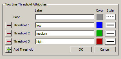
Following is a mockup of a Flow Line Threshold Attribute Editor. This is shown via the ellipsis button on the special rwSetting described in the prior item.
The following eight threshold value rwSetting IDs will be added, for rwSlotValSettings under each Flow Line instance.
The visibility of these will be conditional, based on this new sibling rwIntSetting
The unit type for the threshold values will be based on this new sibling rwEnumSetting:
The latter two rwSettings need to be dynamically set (in each Flow Line instance) when the corresponding count or unit type is set within the containing Flow Line Group.
The FlowLineGfxItem's updateFlowLineItem() method needs to be updated to apply the correct line color and style with respect to where the current series value falls within the flow line thresholds.
Object Icons are a new type of Output Canvas graphics object. Their functionality is mostly a subset of what's currently implemented for teacups, so their implementation can be adapted the current implementation of teacup groups and teacups.
Object Icons will have a loose association with actually simulation objects -- they will be created from a simulation object selection (picked with the GUS object selector). A change in name of a simulation object will also be reflected in corresponding Object Icons. But the deletion of a simulation object will not result in deletion of the icon. (All of this is currently true for a Teacup's releationship to its associated simulation object).
Differences from teacup groups and teacups include:
In the initial provisional development, Flow Lines are stricktly line segments, with two vertices. The coordinates for those two vertices are represented within a Flow Line object with the following four rwIntSettings, with the following IDs:
The rwIntSetting encoding of those values needs to be removed and replaced with a QList of QPoints as a proper C++ data member of the OutputCanvasConfig::FlowLine. The XML serialization of this point list needs to be implemented, accordingly. This can be done as a seperate task before implementing provisions for adding and removing vertices.
The initial provisionally development FlowLineGfxItem class is a subclass of the Qt4 QGraphicsLineItem class. That needs to be reimplemented. The high-level approach is to change that to just a plain, non-rendered QGraphicsItem subclass with a list of child QGraphicsLineItems. That affords us good support for selection and manipuation of individual line segments within the multiple-vertices flow line.
An "Add Node" context menu operation will be added to Flow Line graphical objects. This will just insert an additional anchor point at the clicked point between the two existing anchor points of the Flow Lines line segment closes to that clicked point. The already implemented behavior will allow that anchor point to be dragged to another location.
A new Flow Line Anchor Point context menu operation will be enabled only if there are more than two anchor points (vertices) within the Flow Line.
This new Flow Line Anchor Point context menu operation is a bit more complicated than the other new operations. It puts the Output Canvas Preview into a new mode where:
Lines (or "Callouts?") are a new type of Output Canvas graphics object. Their dynamic functionality is a proper, and small subset of the Task 3 enhancements to Flow Lines. The initial GUI support may be limited to two-point lines if we run out of development time. But multiple vertices (more than two) would make sense for this feature as well.
These lines will initially be implemented with constant display properties (black, and perhaps 2-pixels thick). But if time permits, each Line could have the following attributes, defined with rwSettings. (Note: we could consider defining any of these at the Group level, and allow overrides at the instance level).
Differences from flow line groups and flow lines include:
Note [Phil, 2-13-2015]: An alternative to these free-floating Lines is having one Line optionally associated with the relevant types of Output Canvas graphics objects -- possibly Text items, Object Icons and Teacups. That is, each of those objects could perhaps have ONE optional line which could be made to point to any position on the canvas. I (Phil) kind of prefer this design, but David worries about not giving users control over exact placement of both ends of each line. I can imagine a solution to that concern; we might want to think about this more.
--- (end) ---